


Graphtec FCX Series Flatbed Cutting Plotters and Accessories
FAQ: 0 Questions, 0 Answers
0 Q&As


Item# FCX2000-GRP
- Cutting Speed: 16 inches per second
- Cutting Force: Tool 1: Max. 4.9 N (500 gf) / Tool 2: Max. 9.8 N (1 kgf)
- Ultimate finishing solution for the signage, apparel, and automotive markets
- Available in 3 Different Sizes
Product Name
Item Number
Price
Qty
ProductDescription
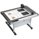
These Graphtec FCX2000 Flatbed Vinyl Cutters and Plotters are the ultimate solution for prototyping and small production runs of rigid packaging media and other sheet fed materials. Its included and dedicated software reduces media waste and processing time. Plus, its added offline, USB operation enables operators of all skill levels to process various types of media for cutting. With Graphtec FCX2000 Flatbed Vinyl Cutters and Plotters, you have the right tool for contour cutting without requiring a die. Available in 24" x 36" , 47.2" x 36" and 68.5" x 36" sizes.
This equipment is a self-installed and self-trained product; in-house technical support is not available. The manufacturer offers online training video’s here.
Product Details
- Stronger Media Hold Down. Distance between the holes has been improved to 20 mm , as a result, FCX2000 Series provides stronger suction power to hold heavier and thicker medias down.
- Improved Vacuum Suction! holds media with the use of external electric vacuum pump. This is the preferred method for heavier and thicker media. The Redesigned Cutting Table has increased hold-down capability by its increased number of vacuum holes. This redesign is significantly valuable when cutting smaller objects that have less of surface area.
- Dual tool holder with 500 gf on tool 1 and 1,000 gf on tool 2
- Provided tools suitable for many applications.
- The FCX2000 series has 2 tool holder in the carriage.
- Using 2 different kind of tool allows to do a different job.
- without exchanging a tool at the same time. it can increase work efficiency.
- Tool Holders & Cutting/Creasing Tools. Dual Tool Holders which can hold a cutting blade and creasing tool — to produce creases/folds and cuts on the same run. Maximum Cutting Force - Tool 1: 500 gf, Tool 2: 1,000 gf.
- Intuitive 3.7” LCD display. Onboard control and settings are simplified using the equipped 3.7” LCD (240x128 dots) and tactile control panel.
- Lope for cutting blade (PM-CT-001). This standard accessory helps to easily adjust the extruded blade lengths for the PHP33 and PHP35 blade holders.
- Offline Operation.
- Enhanced ARMS (Advanced Registration Mark Sensing system) for improved productivity of P&C applications.
- Equipped the ARMS (Advanced Registration Mark Sensing system)6.0.
- Easy and accurate cutting of pre-printed images using the cutting master 4 and etc.
- Enables higher productivity of POP, stickers, and prototype cartons.
- ARMS Copy function. After data is sent the first time, it can be copied multiple times without a PC. In the FCX2000 Series, the first four marks are scanned on the first sheet, and only the first mark in subsequent sheets. This improves productivity by shortening scan detection time.
- Reverse Side Cutting and Creasing Method. Cutting and creasing of pre-printed packaging graphics is possible on the reverse (non-printed) side of the sheet. This method of reverse side cutting and creasing prevents damage and marking of the printed side. This option is currently available using Cutting Master 4 or Graphtec Pro Studio software with the FCX2000.
- Expanded Contour Cutting Area. This included function expands the print and cut area to include objects outside of the registration marks! Production efficiency is enhanced and media waste is reduced.
- Supports Standard Crop Marks. Contour cutting pre-printed media is also possible using “standard crop marks.” This operation is available with the included Cutting Master 4 plug-in workflow.
- Reversed Color Registration Marks. Registraiton marks are detectable when there is sufficient contrast against the mark and its background. Ultra glossy and reflective media offer challenges for accurate registration mark detection. With this reversed color output, the sufficient contrast is brought back for the ability to contour cut pre-printed ultra glossy and reflecting sheeting.
Item Specifications
- Configuration: Digital servo system, Flatbed
- Media hold-down method: Vacuum suction Electrostatic Cling mat / Adhesive sheet
- Mountable media (Y-axis): 950 mm
- Roll media support: Roll media stocker (manual feeding), supported media; width: up to 950 mm, weight: up to 5 kg
- Maximum cutting speed: 16 inches per second
- Cutting force:
- Tool 1: Max. 4.9 N (500 gf)
- Tool 2: Max. 9.8 N (1 kgf)
- Cutting force settings: Tool 1: in 40 steps, Tool 2: in 40 steps
- Minimum character size: Approx. 10 mm square (varies with character font and media)
- Programmable resolution: GP-GL mode: 0.1/0.05/0.025/0.01 mm, HP-GL: 0.025 mm
- Distance accuracy: Max. 0.1% of the distance moved or 0.1 mm, whichever is larger (in plotting mode)
- Perpendicularity: Max 0.5 mm / 900 mm (in plotting mode)
- Repeatability: Max 0.1 mm (excluding contraction of media, in plotting/cutting mode)
- Standard interfaces: RS-232C, USB2.0 (High-Speed), and Ethernet (10BASE-T/100BASE-TX)
- Buffer memory: 2 MB
- Command sets: GP-GL and HP-GL emulation (set by menu, or selects automatically by received data)
- Number of tools: Two tools
- Cutting blade, pen, and tool types: Cutting blade (supersteel), Pens (Water-based fiber-tip pen, oil-based ballpoint pen), and Creasing/scoring tool
- Others: ARMS, Reverse side Cutting/Creasing using ARMS, ARMS Copy function, Creasing, Cutting/creasing in multiple passes
- Power source: 100 to 240 V AC, 50/60 Hz (Auto switching)
- Power consumption: Max. 140 VA
- Operating environment: Temperature: +10 to +35 ºC, Humidity: 35 to 75% RH (non-condensing)
- Guaranteed accuracy environment: Temperature: +16 to +32 ºC, Humidity: 35% to 70% RH (non-condensing)
- Compatible OS: Windows 10 / 8.1 / 8 / 7, Mac OS X 10.6 to macOS 10.12(Graphtec Studio : 10.6-10.12, Cutting Master 4 10.7-10.12)
- Supported software: Cutting Master 4, Graphtec Pro Studio, Graphtec Studio(for Mac)
- Compatible Standards:
- Safety UL60950-1/cUL, CE marking (Low voltage and EMC)
- EMC FCC-A, EN55032-A
- Manufacturer's Warranty: 2 Year Standard
Demonstration Video

Graphtec FCX2000 Tutorial - Assembly
Transcript :
In this lesson we'll cover the assembly of the FCX2000. But before we start it is important to cover some precautions. Once built, place the FCX2000 in an area that is dust free, dry, and is not in direct sunlight. Make sure there's a rated power outlet that is grounded properly for both the cutting plotter and vacuum pump. If possible, leave around 2 to 3 feet of space on each side of the cutter, this makes it easier to load and unload material and reposition the machine. Please avoid storing miscellaneous objects on the table as this may cause damage. Regarding maintenance of the machine do ...
In this lesson we'll cover the assembly of the FCX2000. But before we start it is important to cover some precautions. Once built, place the FCX2000 in an area that is dust free, dry, and is not in direct sunlight. Make sure there's a rated power outlet that is grounded properly for both the cutting plotter and vacuum pump. If possible, leave around 2 to 3 feet of space on each side of the cutter, this makes it easier to load and unload material and reposition the machine. Please avoid storing miscellaneous objects on the table as this may cause damage. Regarding maintenance of the machine do not clean with solvents, the manual recommends a dry cloth or one that has been dampened with a neutral detergent diluted with water. Do not oil the parts, it is absolutely unnecessary and may cause damage. Finally, if something does go wrong don't try to repair. Please call your dealer or Graphtec’s technical support department. There are also a few important precautions to follow when operating the machine, handle the blades with care, they're small and easy to misplace. While this will be covered in a later lesson, also avoid overextending the blade. To prevent injury, stay away from moving parts inevitably something will get torn or pulled. To assemble the machine, start by carefully removing all of the items in the stand box and lay them out in an organized manner. This will help ensure that everything is accounted for. There should be two side panels, two Cross Members, 12 M4 hexagon screws, and four Phillips screws. The next step is building the stand, be aware of the small decals on each of the side panels, these indicate how the table is to be mounted on the stand. Also, as the stand is being assembled, try not to tighten the screws completely yet. This allows the stand to settle correctly once the table is mounted. First, attach one cross member to a side panel then the other cross member to the same panel, and lastly, attach the remaining piece, this completes the stand portion of the assembly. Remove the flatbed table from its box and place it on top of the stand making sure that the decals on the table align with the decals on the stand. Mount it with the provided screws. Once the screws are installed for the table, tighten all of the screws on the stand. Next, mount the bracket and roller on the side of the table. Next, take the pump and install the pipe assembly as seen here. Attach the vacuum hose to the pump, and then to the table. Once the machine is assembled, take the power cord and plug it in securely to the FCX2000 first and then into a rated outlet. Next, take the communication cable, in this case the USB cable, and plug it into the USB port of the FCX2000 and then into your computer. The FCX2000 assembly and setup is now complete. Let's become more familiar with the unit in our next lesson.

Graphtec FCX Series Flatbed Cutting Plotters

Graphtec FCX Series Tutorial - Fundamental Operations
Transcript :
In this lesson, we'll discuss features that are used on a regular basis, such as loading media, adjusting the tool head height, installing the blade correctly, and how to set up conditions at this point, the FCX2000 should be turned on and in ready status. To do this, press the Power Button and wait for the FCX2000 to initialize. Let's start with loading the media. This is a pretty simple operation, but there are some tricks worth taking note of to make loading material easier, the tool head and y bar need to be moved out of the way. Generally, we could use the arrow keys to do this, but the b ...
In this lesson, we'll discuss features that are used on a regular basis, such as loading media, adjusting the tool head height, installing the blade correctly, and how to set up conditions at this point, the FCX2000 should be turned on and in ready status. To do this, press the Power Button and wait for the FCX2000 to initialize. Let's start with loading the media. This is a pretty simple operation, but there are some tricks worth taking note of to make loading material easier, the tool head and y bar need to be moved out of the way. Generally, we could use the arrow keys to do this, but the best way is to use the View Option. Which will move the tool head all the way to the upper right hand corner, while in ready status, pressing the one key activates the view mode. Once the y bar is completely out of the way, media can easily be placed when placing the media on the bed, position it so that it is closest to the control panel in the lower left hand corner. The FCX2000 is equipped with a redesigned table where the vacuum holes are closer together, providing stronger media hold down for smaller objects. It sometimes helps to place an additional larger sheet over your design to ensure stable suction. Once the sheet is placed on the table and correctly positioned, press the vacuum pump pedal switch to activate the vacuum, and then press the two key for home to bring the tool head back to the origin. If you are using a roll of media, take the roll of media and place it onto the media stock roller and place the media roll and roller bar back in place. Pull the edge of the media from the roll. Carefully thread the front edge of the media under the y bar, and pull the material across the table. Once it reaches the other side, activate the vacuum pump using the pedal switch. There will be times when the tool head height will have to be adjusted according to the thickness of the material. This is generally done when switching between materials that have a significant difference in thicknesses. You'll have to make this determination yourself, but cutting operations may be affected if the head height is not set correctly to raise or lower the tool head. First, move the tool head toward the middle of the bed. Next, loosen the two side screws on each side of the tool head using the supplied hex tool. Once the screws are loosened, lift the head and place the block spacer that was supplied with the unit under the tool head. Lower the tool head onto the block, making sure that it's flat against the block. Then tighten the screws and remove the orange block. Next, locate the blade holder you plan to use and remove the cap, exposing the tip of the blade holder. Remove the brass tip chuck from the blade holder by unscrewing it counterclockwise, locate the CB15U container. Carefully remove the blade from the container and remove the plastic cover, insert it into the blade holder, Chuck as shown here, screw the chuck back onto the blade holder. Extend the blade to the thickness of the media. Place the blade holder tip next to the media you plan to cut. This should give you a general indication of how far to extend the blade. Further test the length by test cutting a piece of the material you plan to use by laying the material flat on a table. Then, with the blade holder tool in your hand, draw a circle on the material as you're drawing the circle, make sure the tool head is in a straight, upright position and not at an angle. Remove the circle. It should come out relatively easily. If it is difficult to remove, then extend the blade by turning the adjustment knob one quarter of an inch clockwise and repeat the test. If you are cutting media with a carrier sheet, reach on the backside of the media or vinyl, and with your hand, try to push up from the backside of the media under the cut circle. If it pops out easily, then the blade is extended too far, retract the blade by turning the adjustment knob one quarter of an inch, counter clockwise and repeat the test. A bid for checking materials without a backing, such as chipboard or corrugated packaging material, is to place the blade at the edge of the material and cut it if it splits easily, then the blade is adjusted correctly. Once the blade is extended properly, loosen the tool holder screw enough so that the bracket is out of the way and insert the blade holder onto the tool holder mount. If this is not done correctly, the blade will not reach the media. Then tighten. Graphtec offers several tools for cutting, creasing and plotting. If you are wondering which one to use in their respective settings, you can download a tool list from Graphtec?s e-commerce website at www.graphtecamericastore.com, two of the accessories provided with the FCX2000 are a Pen Holder and Fiber-Tipped Pen. To use a pen, First, loosen the lock handle by twisting it counterclockwise. Next, take the fiber-tipped pen that came with the cutter and insert it into the adapter. Then re-tighten the lock handle. Next, insert the adapter and pen into a tool holder, the same way that a blade holder is installed. Generally, Tool Holder 1 is preferred, especially when a cutting or creasing tool is also being used. Once again, push the pen adapter all the way down until the rim is completely seated and is under the top of the bracket. And tighten, one great feature of all Graphtec cutters are the utilization of conditions. A Condition is a plotting cutting preset that can be configured for a specific type of material or job. For instance, Condition one can be configured for drawing with a pen, whereas Condition two may be configured for cutting and Condition three can be configured for creasing. One cutting condition may be set for cutting sandblast while another to cutting reflective material or chipboard. Conditions can even be configured to a specific type of cutting, for instance, while condition one can be configured for cutting sandblast. Condition two can be configured for intricate cutting of sandblast, perhaps requiring slower speeds around the corners. The FCX2000 has eight cutting conditions. Each condition has 4 main settings, Tool Type, Speed, Force and Acceleration. There are other settings as well, such as tangential mode for cutting cleaner corners on thicker materials. Since there are 2 tool holders, each condition is assigned to either Tool Holder 1 or Tool Holder 2, depending on the operation recall that tool or two has the higher force of one kilogram. This means that certain conditions configured to cut thick or rigid materials may have to use Tool Holder 2. Let's first take a look at how to configure and test the condition, and then how to switch between conditions. The control panel display will show us information at a quick glance that we need to know. For instance, right now, the cutters display shows the current condition. Just below the condition number are the condition settings of the current selection. So right now, Condition one has the tool type of a CB15U blade. S is the speed, which is 40 centimeters per second, referring to the speed when the pen is in the down position. F is the force, which is set to 38 relating to how much downward force the tool exerts. As a note, the force value can be set up so that it will cut with different values in the x and y directions, as shown here. This feature will be discussed later in this lesson, the last acceleration currently at 4, indicating how quickly the cutter speed is reached after the cutting tool changes direction. Next is to configure the current condition settings. By pressing the condition slash test key in this menu, we are given different settings, condition, number, tool, type, speed and force. Notice for this menu, there are also four pages of options. If we press the Up or Down arrow key, we can cycle through the pages of other condition settings. In this example, we're going to set a condition for cutting vinyl. First, we need to select the tool type by pressing the two key and this tool menu appears pressing the up and down arrow keys cycles through the different tool types. In this case, the type that will be used is the CB15U which was the tool type already selected. This tool comes standard with the FCX2000 if you are unsure of which tool type is which, check the package it came in. Now that we have selected the tool type, simply press the Enter key to set the tool type. This will bring us back to the condition one settings. We can keep the speed the same, but let's change the force to a value of 20 by pressing the four key. This menu is a little different from the tool type menu. Here we are given all the force values for each condition. The top row of numbers represents each of the eight conditions. The bottom row of numbers represents the force values of each condition right now, condition one is highlighted. This means that we can change the force value for condition one. We can press the down arrow key to lower it to 20 if we wanted to change the force for condition three. Here, we can do it on the fly by pressing the side arrow key for now we will leave it as is. Let's go back to the one for condition one now that the force is adjusted to 20, pressing Enter sets the value. Once a condition is configured, it should be tested. At the lower right of the display shows two different types of test patterns to cut. If the left arrow is pressed, the cutter will cut a single square paired with a triangle. The right arrow key will cut three patterns. The first pattern is cut with the current force minus one. For instance, the force is set to the value of 20, then the first pattern is cut with the force value of 19. The middle pattern is cut at the current force of 20, and the third pattern is cut at the current force plus one. In this case, 21 this provides a way to more accurately determine the necessary value, if you are cutting adhesive back media. This may be the pattern you'd want to use until you become more familiar with the operation of the cutter when cutting thicker materials, one pattern makes a vice. Let's press the right arrow, press the one key for force, since that is what we are testing, this will cut three patterns on vinyl for materials with a backing, such as self-adhesive vinyl, once the pattern, or patterns are cut, First, remove the square in the middle pattern, it should separate from the triangle fairly easily, if not try the third pattern. If it removes easily, we know to increase the force by one when cutting a test pattern on materials, you plan to cut all the way through, such as material without a packing, the entire pattern should pop out, leaving clean edges. Don't concern yourself with leaving the triangle as long as the square pops out easily. Then the cutting force is set correctly. Once you understand how to adjust the condition, the next step is to configure the other conditions. Let's switch to a different condition. This is easily done by pressing the one key for condition. Here we can switch to a different condition by pressing the Up or Down arrow key. This will cycle through the eight conditions. Let's cycle through to condition two and configure condition two for cutting chipboard. We'll set the tool to CB15U the speed to 35 and the Force to 20, press enter to set the values and finally let's set condition three for creasing. Press the one key to change the condition. Next, press the up arrow and switch it to condition three. Press Enter and adjust the setting for creasing. We'll set the tool to CT-002, we need to set the creasing pressure relatively high, so before we set the force, we have to assign condition three to tool holder two. This way we can take advantage of its higher force. Press the up arrow key once to access the next page of settings to assign condition three to tool holder two. We need to press the two key for assign tool once again, we have this matrix similar to when we change the force, except the bottom row of numbers represent which tool holder is assigned to each condition. A one represents tool holder one, and a two represents tool holder two. Since the highlighted condition is set to three, we can press the up or down arrow to set the value to two, representing tool holder two, and press enter. Now we can change the rest of the condition settings, including the force, now that it can be set to a higher force value of 70, and set the speed. To get back to the status, press the condition slash test key when the cutter status is ready. The quickest way to switch conditions is simply by holding the enter key and selecting the appropriate condition from the pop up window beside each condition, there is a key number or arrow key, showing us what to Press to switch to that condition. Keys one through four will switch to conditions one through four, respectively, four press one of the arrow keys for conditions five through eight. Let's press the two key to jump to condition two, as you will learn in later lessons. Switching conditions can also be done completely from the cutting master or plugin. Configuring conditions may seem tedious at first, but in the long run, it can save you a lot of time and hassle. For instance, each time you switch materials, instead of taking the time to configure the cutter to the best setting each time a new material is loaded, it's simply a matter of switching to a condition that has been perfectly configured to that material. Add to this the idea of assigning conditions to individual paths within the software, and it will make you even more productive. Selecting the appropriate condition from the pop up window beside each condition, there is a key number or arrow key, showing us what to Press to switch to that condition. Keys one through four will switch to conditions one through four, respectively, or press one of the arrow keys for conditions five through eight, showing us what to Press to switch to that condition. Keys one through four will switch to conditions one through four respectively, or press one of the arrow keys for conditions five through eight. Let's press the two key to jump to condition two, as you will learn in later lessons. Switching conditions can also be done completely from the cutting master or plugin. Configuring conditions may seem tedious at first, but in the long run, it can save you a lot of time and hassle. For instance, each time you switch materials, instead of taking the time to configure the cutter to the best setting each time a new material is loaded, it's simply a matter of switching to a condition that has been perfectly configured to that material. Add to this the idea of assigning conditions to individual paths within the software, and it will make you even more productive. Tangential mode is a cutting method listed in the condition settings used to provide cleaner corners for thicker materials. When enabled, the cutting blade is lifted up on each corner, swiveled to the next direction, then comes down with the blade positioned in the direction of the next line segment. Tangential mode is a condition setting which you may choose to enable or disable for each condition based on the material you plan to use to turn on tangential mode for a specific condition, press the condition slash test key recall that this will allow us to adjust the setting for each condition. If we press the up arrow key to display the second page of settings, we can then press the three key for tangential mode. Once again, we are showing the matrix of the eight conditions, with the bottom row indicating whether thick is enabled or disabled for each condition. A dashed line shows that tangential mode is disabled for that condition. A one represents that tangential mode is enabled for that condition and that it is set to mode one, a two represents that tangential mode is enabled and is using mode two. What is the difference between mode one and mode two? When tangential mode is enabled, it overcuts the corners. In other words, the blade will cut past each corner, thus providing sharper corners. Mode one will overcut each corner of the design, whereas mode two overcuts only the start and end points. Mode one is best used for thicker materials such as sandblast rubber or corrugated packaging for thin materials such as cutting intricate lettering or graphics on self-adhesive vinyl mode. Two can be used, since over cutting is not necessarily needed. In this case, we'll press the one key, since we are cutting chipboard. Finally, press Enter to apply the changes. When using tangential mode, the amount of overcut can be adjusted depending on the material being cut while we are still in condition settings, if the four key is pressed, this will allow for the overcut lengths to be set. Pressing two allows us to set the distance the cutter starts each cut line before the intended start point of the line segment, whereas pressing the three key will allow us to have the cutter extend the cut line beyond the intended endpoint of the line segment. Generally, the default values are sufficient for most materials, but cutting thicker materials may require the extension of each cut line. One improvement of the FCX2000 is its expanded creasing capabilities due to its high rigidity, y bar optimized algorithms and a new creasing tool providing smoother creasing Graphtec?s newest creasing tool, the CT-001, has been completely redesigned to produce cleaner crease lines and the ability to create curved crease lines, which allows for more flexible and creative packaging design. In this section we will cover the different creasing tools available, as well as some of the options available for creasing. There are two types of creasing tools. The first type is for creasing thick card such as chipboard. These crease tools use a small rolling bar at their tips to crease the material. The second type of tool is for corrugated packaging materials. These creasing tools use a wheel to crease the material. Generally, both tools need high force to work properly, so it is best to load them in tool holder two which has higher down force. Installing a creasing tool is similar to installing a blade holder tool. Loosen the thumb screw, insert the creasing tool. Make sure the tool is seated all the way to the bottom, and then tighten the thumb screw, making sure the top of the bracket is over the rim of the crease tool. The next step is to configure a condition for it. In this example, since we will be using chipboard, we have already configured condition two for cutting and condition three for creasing chipboard to save time. We've already configured the speed and force. Let's go ahead and configure the other settings for using a creasing tool by cycling to page three of four of the condition Settings and press the one key for crease conditions. Here are our options directly affecting the crease line. The first option mode has different types of crease lines. Let's press the two key, and here we can cycle through modes one through three. The difference between each mode is simple. Let's say this is the intended line data that is to be the crease line. If mode one is chosen, a single crease line is placed or plotted on the intended line data. If mode two is chosen, crease lines are placed or plotted on either side of the intended line. If mode three is chosen, the crease line is placed or plotted on the intended line pattern, as well as plotted on each side of the intended line pattern. Using one of these two modes provides a rounded look to the crease lines. Spacing determines the space between the two crease lines when modes two and three are being used, let's press the Escape key to adjust the spacing. The right arrow key can be pressed, which will bring up this window where the Up and Down arrow key changes the spacing. Let's go back by pressing Escape, repeats tells the cutter to make additional passes of crease line to the number indicated by pressing the three key, we can increase the number of repeats we want for each crease line. Let's go back by pressing Escape, the start option determines the length of the line. The higher the number, the shorter the crease line will be, creating a gap at each end of a line segment. Once all settings are adjusted to your preferences, press Enter to apply the values. Of course, the next step is to test the condition. This is done by pressing the left arrow key, and the cutter will plot a pattern using the current condition settings, as seen here the creasing tool is doing the repeats that we specified earlier. This may be sufficient, however, we recommend doing further testing by sending a design with crease lines using a sheet of the material you plan to process the next section will cover some of the commonly cut materials for the FCX2000 for each material, we will supply the tools needed as well as some suggestions when cutting them. Please keep in mind that these values and settings provided by Graphtec are to serve only as guide points, since each material specifications can vary greatly depending on its manufacturer. Graphtec offers a multitude of blades and tools for use with different types of media you may be using. This diagram can also be found on Graphtec?s website to review the details of each tool and blade the general steps to take prior to cutting each material are, first set up the blade you plan to use, adjust and test the blade length of the blade tool holder, adjust the tool head to the correct height if necessary, configure a condition for cutting the material, and finally, perform a test cut. The items that are needed to cut sandblast rubber are the CB15U- K30, that comes standard with the FCX2000 and the pen adapter and pen the reason we suggest using the pen tool with sandblast is because once the pattern is cut, is difficult to see where the cut line is. When it is time to weed the design, we suggest using the pen to first plot the pattern and then follow-up with a second pass using the cutting tool. When a pattern is plotted with a pen and then cut, it provides an easy way to distinguish the cut lines. Being a thicker media, Tangential mode should be enabled for that condition. When cutting chipboard or corrugated packaging material, the CB15U can be used and for thicker materials the CB15U- K30 both come standard with the FCX2000. Graphtec offers a larger blade the CB30UC. If you plan to order this particular blade, a different blade holder must also be ordered, as mentioned earlier in the section on creasing Graphtec offers four different creasing tools. The first two, the CP001, and the CT001, are rollerball types that are meant to be used only with chipboard, and the roller wheel type for corrugated material. When configuring the conditions, make sure tangential mode is enabled using mode one when cutting corrugated materials, it may be suitable to enable switching X,Y force options. This allows for separate force values for the x or horizontal direction and the y vertical direction. To enable this option. Press the pause menu key, the down arrow key for advanced options, the up arrow key for the next page of options. Press the one key for switching X, Y, force option. The one key again to enable it, the enter key to apply the option, and lastly, press the pause menu key to place the cutter in ready status. When changing the force, there will be two values to adjust for both the x and y directions. To cut magnetic material, the standard CB15U blade can be used. Magnetic material does not have to be completely cut through, like other materials, generally, only a good scoring is required. Keep this in mind when configuring the conditions force value as with other thicker materials, it is best to enable tangential mode using mode two, since overcuts on each corner are generally not needed. Offset blankets are generally thicker, so the CB15U- K30 is the best blade to use when configuring this condition, enable tangential mode using mode one, as mentioned earlier, we have not recommended specific condition settings. This is something you will have to adjust firsthand. We do recommend that before cutting or creasing on your SCX2000 configure a condition for each media you plan to use, this will make production more efficient and guarantee consistent cutting increasing.
Compare to Similar Graphtec Flatbed Vinyl Cutters and Plotters
| Model Name | Graphtec FCX2000-60VC | Graphtec FCX2000-120VC | Graphtec FCX2000-180VC | Graphtec FCX4000-50 | Graphtec FCX4000-60 |
|---|---|---|---|---|---|
| Model | 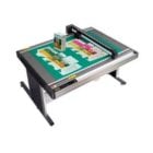 |
 |
 |
 |
 |
| Effective cutting area | 24" x 36" | 47.2" x 36" | 68.5" x 36" | 25.98" x 19.21" (W x H) | 38.42" x 25.98" (W x H) |
| Mountable media (Y-axis) | 950 mm | 950 mm | 950 mm | 21.10" | 27.97" |
| Maximum cutting speed | 16 inches per second | 16 inches per second | 16 inches per second | 29.5"/s (1 to 75 cm/s in 23 steps) | 29.5"/s (1 to 75 cm/s in 23 steps) |
| Cutting force | Tool 1: Max. 4.9 N (500 gf) / Tool 2: Max. 9.8 N (1 kgf) | Tool 1: Max. 4.9 N (500 gf) / Tool 2: Max. 9.8 N (1 kgf) | Tool 1: Max. 4.9 N (500 gf) / Tool 2: Max. 9.8 N (1 kgf) | Tool 1: Max. 5.88 N (600 gf) / Tool 2: Max. 5.88 N (600 gf) | Tool 1: Max. 5.88 N (600 gf) / Tool 2: Max. 5.88 N (600 gf) |
| Distance accuracy | Max. 0.1% of the distance moved or 0.1 mm, whichever is larger (in plotting mode) | Max. 0.1% of the distance moved or 0.1 mm, whichever is larger (in plotting mode) | Max. 0.1% of the distance moved or 0.1 mm, whichever is larger (in plotting mode) | Max.0.2% of the distance moved or 0.1mm, whichever is larger (excluding contraction of media, in plotting/cutting mode) | Max.0.2% of the distance moved or 0.1mm, whichever is larger (excluding contraction of media, in plotting/cutting mode) |
| Distance accuracy | Max. 0.1% of the distance moved or 0.1 mm, whichever is larger (in plotting mode) | Max. 0.1% of the distance moved or 0.1 mm, whichever is larger (in plotting mode) | Max. 0.1% of the distance moved or 0.1 mm, whichever is larger (in plotting mode) | Max.0.2% of the distance moved or 0.1mm, whichever is larger (excluding contraction of media, in plotting/cutting mode) | Max.0.2% of the distance moved or 0.1mm, whichever is larger (excluding contraction of media, in plotting/cutting mode) |
| Perpendicularity | Max 0.5 mm / 900 mm (in plotting mode) | Max 0.5 mm / 900 mm (in plotting mode) | Max 0.5 mm / 900 mm (in plotting mode) | Max 0.3 mm / 16.93" (excluding contraction of media, in plotting/cutting mode) | Max 0.3 mm / 16.93" (excluding contraction of media, in plotting/cutting mode) |
| Power consumption | Max. 140 VA | Max. 140 VA | Max. 140 VA | Max. 120 VA | Max. 120 VA |